 indicates the item is supported by N 1~3K seriesindicates the item is supported by N 1~3K series
 indicates the item is supported by L series
1.0 |
09/23/1997 |
|
1.1 |
11/14/1997 |
|
1.2 |
12/30/1997 |
Add VSN(Voltage Sensitivity) |
1.3 |
10/09/1998 |
Control Outlet Add Regular Format ID Add TEL, BRD commands |
1.31 |
01/26/1999 |
SDR from 99999 to 65535 |
1.32 |
03/04/1999 |
Add STA---Inverter Bad |
1.33 |
04/28/1999 |
Add ENV, Battery Level, Rating Battery Voltage Mark some items that UPS must support |
1.34 |
05/03/1999 |
Change BUZ Status(0: Buzzer off, 1:Buzzer on) |
1.35 |
07/21/1999 |
Economic Mode enable/disable Periodic Auto-test Buzzer Test ATX Reboot enable/disable Auto Reboot enable/disable |
1.36 |
07/28/1999 |
Add RSM---Resume PC, AVL rearrange |
1.37 |
08/17/1999 |
Change Length of MNU, MOD and VER to 16 Change Range of RNF from 1 to 65535 |
1.38 |
05/09/2000 |
Add the Emergency Power Off item in the STA |
1.39 |
04/03/2001 |
Add TXF(Raymond), UBD Commands Define the ARB command |
1.40 |
07/18/2001 |
Add SOV command |
1.41 |
01/25/2002 |
Delete the RST command because it is conflict to the ARB command. Redefine BUZ command to alarm/silence Add EDB command to enable/disable buzzer alarm Define a standard string of Windows Plug & Play |
1.42 |
01/30/2002 |
Redefine 'Battery Temperature' to 'Temperature' |
1.44 |
05/24/2002 |
Add BTV command for battery test |
Baud Rate 2400
Parity None
Data Bits 8
Stop Bits 1
h4>2.Message Format
| Header | ID | Type | Length | Data |
|---|---|---|---|---|
| 1 byte | 2 bytes | 1 byte | 3 bytes | 128 bytes max |
| Command | Description |
|---|---|
| * AVL |
Available Commands |
| * MNU |
UPS Manufacturer |
| * MOD |
UPS Model Name |
| * RAT |
Rating(Nominal) Values |
| SDT | Shutdown Type |
| * STB |
Battery Status |
| * STI |
Input Status |
| * STO |
Output Status |
| * STP |
Bypass Status |
| * STA |
Alarm Status |
| * TSR |
Self Test Results |
| UBR | UPS Baud Rate |
| * UID | UPS Identification |
| * VER |
UPS Firmware Version |
| TXV |
Transfer Voltage |
| VSN |
Voltage Sensitivity |
| * LET |
Number of Outlet Relay |
| * SOL |
Outlet Relay Status |
| TEL | Modem Phone Number |
| * BRD |
Battery Replacement Date |
| ENV | Environment Information |
| ATT | Auto Test |
| ATX |
ATX Reboot enable/disable |
| ARB |
AC Fail & Restore Auto-Reboot enable/disable |
| TXF | Transfer Frequency |
| UBD | UPS Boot Delay |
| SOV | Select Output Voltage |
| BTV | Battery Test Time & Voltage |
| Name | Type | Range/Length | Comment | Software |
|---|---|---|---|---|
| b19 b18 b17 b16 b15 b14 b13 b12 b11 b10 b9 b8 b7b6 b5 b4 b3 b2 b1 b0 | Integer | 20 | 1 = Available 0 = Not supported |
| Name | Type | Range/Length | Comment | Software |
|---|---|---|---|---|
| Manufacturer | String | 0 to 16 |
Description: The string identifies the manufacturer.
| Name | Type | Range/Length | Comment | Software |
|---|---|---|---|---|
| Model | String | 0 to 16 |
Description: The string identifies the UPS model name.
|
Name |
Type |
Range/Length |
Comment |
Software |
|
* Rating Input Voltage |
Integer |
0 to 999 |
Volt |
|
|
* Rating Input Frequency |
Integer |
0 to 999 |
0.1Hz |
|
|
Rating Output Voltage |
Integer |
0 to 999 |
Volt |
|
|
Rating Output Frequency |
Integer |
0 to 999 |
0.1Hz |
|
|
* Rating VA |
Integer |
0 to 999999 |
VA |
|
|
Rating Output Power |
Integer |
0 to 999999 |
Watt |
|
|
Low Battery Time |
Integer |
0 to 99 |
Minute, time from low battery to low battery shutdown |
|
|
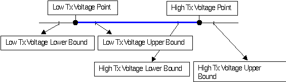
Low Tx Voltage Point |
Integer |
0 to 999 |
Volt |
|
|
High Tx Voltage Point |
Integer |
0 to 999 |
Volt |
|
|
Low Tx Voltage Upper Bound |
Integer |
0 to 999 |
Volt |
|
|
Low Tx Voltage Lower Bound |
Integer |
0 to 999 |
Volt |
|
|
High Tx Voltage Upper Bound |
Integer |
0 to 999 |
Volt |
|
|
High Tx Voltage Lower Bound |
Integer |
0 to 999 |
Volt |
|
|
* UPS Type |
Integer |
0 to 4 |
0: On-Line 1: Off-Line 2: Line-Interactive 3: 3 Phase 4: Others |
|
|
* Rating Battery Voltage |
Integer |
0 to 999 |
Volt |
|
|
Low Tx Freq Point |
Integer |
0 to 999 |
0.1Hz |
|
|
High Tx Freq Point |
Integer |
0 to 999 |
0.1Hz |
|
|
Low Tx Freq Upper Bound |
Integer |
0 to 999 |
0.1Hz |
|
|
Low Tx Freq Lower Bound |
Integer |
0 to 999 |
0.1Hz |
|
|
High Tx Freq Upper Bound |
Integer |
0 to 999 |
0.1Hz |
|
|
High Tx Freq Lower Bound |
Integer |
0 to 999 |
0.1Hz |
|
Description: The Tx voltage
3.1.5 SDT
Data: (UPS->Computer)
|
Name |
Type |
Range/Length |
Comment |
Software |
|
Shutdown Type |
Integer |
1 to 2 |
1 = UPS output 2 = UPS system |
|
Description: default value is 2.
3.1.6 STB
Data: (UPS->Computer)
|
Name |
Type |
Range/Length |
Comment |
Software |
|
* Battery Condition |
Integer |
0 to 2 |
0 = Good 1 = Weak 2 = Replace |
|
|
* Battery Status |
Integer |
0 to 2 |
0 = OK 1 = Low 2 = Depleted |
|
|
* Battery Charge |
Integer |
0 to 3 |
0 = Floating 1 = Charging 2 = Resting 3 = Discharging |
|
|
Seconds on Battery |
Integer |
0 to 99999 |
Seconds |
|
|
Estimated Minutes Remaining |
Integer |
0 to 9999 |
Estimated time from backup to low battery shutdown. |
|
|
Estimated Charge Remaining |
Integer |
0 to 999 |
Estimated of percent battery charge remaining. |
|
|
Battery Voltage |
Integer |
0 to 9999 |
0.1Volt |
|
|
Battery Current |
Integer |
0 to 9999 |
0.1Amp |
|
|
Temperature |
Integer |
0 to 999 |
Degree Celsius |
|
|
* Battery Level |
Integer |
0 to 999 |
% |
|
Description:
Battery Condition: If input power normal and battery normal then UPS replies Good(0). If input power normal and battery low then Weak(1) is replied.
Battery Status: The indication of the capacity remaining in the batteries.
Estimated Minutes Remaining: Estimated time from backup to low battery shutdown base on the current load.
Estimated Charge Remaining: An estimate of the battery charge remaining expressed as a percent of full charge.
Temperature: The temperature value that is measured in the UPS.
3.1.7 STI
Data: (UPS->Computer)
|
Name |
Type |
Range/Length |
Comment |
Software |
|
* Input Num Lines(Phases) |
Integer |
0 to 9 |
Number of input lines |
|
|
Input Frequency1 |
Integer |
0 to 999 |
0.1Hz |
|
|
Input Voltage1 |
Integer |
0 to 9999 |
0.1Volt |
|
|
Input Current1 |
Integer |
0 to 9999 |
0.1Amp |
|
|
Input Power1 |
Integer |
0 to 99999 |
Watt |
|
|
Input Frequency2 |
Integer |
0 to 999 |
0.1Hz |
|
|
Input Voltage2 |
Integer |
0 to 9999 |
0.1Volt |
|
|
Input Current2 |
Integer |
0 to 9999 |
0.1Amp |
|
|
Input Power2 |
Integer |
0 to 99999 |
Watt |
|
|
Input Frequency3 |
Integer |
0 to 999 |
0.1Hz |
|
|
Input Voltage3 |
Integer |
0 to 9999 |
0.1Volt |
|
|
Input Current3 |
Integer |
0 to 9999 |
0.1Amp |
|
|
Input Power3 |
Integer |
0 to 99999 |
Watt |
|
3.1.8 STO
Data: (UPS->Computer)
|
Name |
Type |
Range/Length |
Comment |
Software |
|
* Output Source |
Integer |
0 to 5 |
0 = Normal 1 = Battery 2 = Bypass(Reserve) 3 = Reducing 4 = Boosting 5 = Manual Bypass 6 = Other 7 = None |
|
|
Output Frequency |
Integer |
0 to 999 |
0.1Hz |
|
|
* Output Num Lines(Phase) |
Integer |
0 to 9 |
Number of output lines |
|
|
Output Voltage1 |
Integer |
0 to 9999 |
0.1Volt |
|
|
Output Current1 |
Integer |
0 to 9999 |
0.1Amp |
|
|
Output Power1 |
Integer |
0 to 999999 |
Watt |
|
|
* Output Load1 |
Integer |
0 to 999 |
Percent |
|
|
Output Voltage2 |
Integer |
0 to 9999 |
0.1Volt |
|
|
Output Current2 |
Integer |
0 to 9999 |
0.1Amp |
|
|
Output Power2 |
Integer |
0 to 999999 |
Watt |
|
|
Output Load2 |
Integer |
0 to 999 |
Percent |
|
|
Output Voltage3 |
Integer |
0 to 9999 |
0.1Volt |
|
|
Output Current3 |
Integer |
0 to 9999 |
0.1Amp |
|
|
Output Power3 |
Integer |
0 to 999999 |
Watt |
|
|
Output Load3 |
Integer |
0 to 999 |
Percent |
|
Description: Output Source: On-Line UPS status will be 0, 1, 2
Off-Line UPS status will be 1, 2, 3, 4
3 Phase UPS status will be 0, 1, 2, 5
The present source of output power.
3.1.9 STP
Data: (UPS->Computer)
|
Name |
Type |
Range/Length |
Comment |
Software |
|
Bypass Frequency |
Integer |
0 to 999 |
0.1Hz |
|
|
* Bypass Num Lines(Phase) |
Integer |
0 to 9 |
Number of bypass lines |
|
|
Bypass Voltage1 |
Integer |
0 to 9999 |
0.1Volt |
|
|
Bypass Current1 |
Integer |
0 to 9999 |
0.1Amp |
|
|
Bypass Power1 |
Integer |
0 to 999999 |
Watt |
|
|
Bypass Voltage2 |
Integer |
0 to 9999 |
0.1Volt |
|
|
Bypass Current2 |
Integer |
0 to 9999 |
0.1Amp |
|
|
Bypass Power2 |
Integer |
0 to 999999 |
Watt |
|
|
Bypass Voltage3 |
Integer |
0 to 9999 |
0.1Volt |
|
|
Bypass Current3 |
Integer |
0 to 9999 |
0.1Amp |
|
|
Bypass Power3 |
Integer |
0 to 999999 |
Watt |
|
3.1.10 STA
Data: (UPS->Computer)
|
Name |
Type |
Range/Length |
Comment |
Software |
|
Alarm Temperature |
Integer |
0 or 1 |
0 = OK 1 = Over Temperature |
|
|
Alarm Input Bad |
Integer |
0 or 1 |
0 = OK 1 = Input Bad |
|
|
Alarm Output Bad |
Integer |
0 or 1 |
0 = OK 1 = Output Bad |
|
|
Alarm Overload |
Integer |
0 or 1 |
0 = OK 1 = Overload |
|
|
Alarm Bypass Bad |
Integer |
0 or 1 |
0 = OK 1 = Bypass Bad |
|
|
Alarm Output Off |
Integer |
0 or 1 |
0 = Output On 1 = Output Off |
|
|
Alarm UPS Shutdown |
Integer |
0 or 1 |
0 = OK 1 = Shutdown |
|
|
Alarm Charger Failure |
Integer |
0 or 1 |
0 = OK 1 = Charger Failed |
|
|
Alarm System Off |
Integer |
0 or 1 |
0 = System On 1 = System Off |
|
|
Alarm Fan Failure |
Integer |
0 or 1 |
0 = OK 1 = Fan Fault |
|
|
Alarm Fuse Failure |
Integer |
0 or 1 |
0 = OK 1 = Fuse Fault |
|
|
Alarm General Fault |
Integer |
0 or 1 |
0 = OK 1 = General Fault |
|
|
Alarm Awaiting Power |
Integer |
0 or 1 |
0 = OK 1 = Awaiting Power |
|
|
Alarm Shutdown Pending |
Integer |
0 or 1 |
0 = OK 1 = Shutdown Pending |
|
|
Alarm Shutdown Imminent |
Integer |
0 or 1 |
0 = OK 1 = Shutdown Imminent |
|
|
Buzzer Status |
Integer |
0 or 1 |
0 = UPS Buzzer Silence 1 = UPS Buzzer Alarm |
|
|
Economic Mode |
Integer |
0 or 1 |
0 = No 1 = Yes |
|
|
Alarm Inverter Bad |
Integer |
0 or 1 |
0 = No 1 = Yes |
|
|
Emergency Power Off |
Integer |
0 or 1 |
0 = Off 1 = On |
|
|
Buzzer State |
Integer |
0 or 1 |
0 = UPS Buzzer Disable 1 = UPS Buzzer Enable |
|
Description:
Alarm Input Bad: An input condition is out of tolerance. This item is used to indicate the input power fail, a test condition should not set this item on.
Alarm Output Bad: An output condition (other than OutputOverload) is out of tolerance.
Alarm Overload: The output load exceeds the UPS output capacity.
Alarm Bypass Bad: The Bypass is out of tolerance.
Alarm Output Off: The UPS has shutdown as requested, i.e., the output is off.
Alarm UPS Shutdown: The entire UPS has shutdown as commanded.
Alarm Charger Failure: An uncorrected problem has been detected within the UPS charger subsystem.
Alarm System Off: The UPS system is in the off state. For example: The UPS get the input power but does not startup the system.
Alarm Fan Failure: The failure of one or more fans in the UPS has been detected.
Alarm Fuse Failure: The failure of one or more fuses has been detected.
Alarm Awaiting Power: The UPS output is off and the UPS is awaiting the return of input power.
Alarm Shutdown Pending: A shutdown UPS command SDA countdown is underway.
Alarm Shutdown Imminent: The UPS will turn off power to the load in less than 5 seconds; this may be either a timed shutdown or a low battery shutdown.
Alarm Buzzer Status: To indicate the UPS buzzer is silent or alarm.
Economic Mode: The UPS is in the economic mode (act like a off-line UPS).
Emergency Power Off: The User pressed the Emergency Power Off button.
Alarm Buzzer State: To indicate the UPS buzzer is enabled or disabled.
3.1.11 TSR
Data: (UPS->Computer)
|
Name |
Type |
Range/Length |
Comment |
Software |
|
* Test Result |
Integer |
0 to 5 |
0 = No test performed 1 = Test passed 2 = Test in progress 3 = General test failed 4 = Battery test failed 5 = Deep batt test failed 6 = Test Aborted |
|
3.1.12 UBR
Data: (UPS->Computer)
|
Name |
Type |
Range/Length |
Comment |
Software |
|
Baud Rate |
Integer |
See Comment |
1200,2400,4800,9600 |
|
Default: 2400
3.1.13 UID
Data: (UPS->Computer)
|
Name |
Type |
Range/Length |
Comment |
Software |
|
UPS Identification |
Integer |
0 to 99 |
Used for one PC connect to multi-UPS |
|
Default: 0
3.1.14 VER
Data: (UPS->Computer)
|
Name |
Type |
Range/Length |
Comment |
Software |
|
UPS Firmware Version |
String |
0 to 16 |
|
|
3.1.15 TXV
Data: (UPS->Computer)
|
Name |
Type |
Range/Length |
Comment |
Software |
|
Low Transfer Voltage |
Integer |
0 to 999 |
Volt |
|
|
High Transfer Voltage |
Integer |
0 to 999 |
Volt |
|
3.1.16 VSN
Data: (UPS->Computer)
|
Name |
Type |
Range/Length |
Comment |
Software |
|
Voltage Sensitivity |
Integer |
0 to 2 |
0 = Normal 1 = Reduced 2 = Low |
|
3.1.17 LET
Data: (UPS->Computer)
|
Name |
Type |
Range/Length |
Comment |
Software |
|
Number of Output Relay |
Integer |
0 to 99 |
0 = Not available >0 Available |
|
3.1.18 SOL
Data: (Computer->UPS)
|
Name |
Type |
Range/Length |
Comment |
Software |
|
Index of Output Relay |
Integer |
1 to 99 |
|
|
Data: (UPS->Computer)
|
Name |
Type |
Range/Length |
Comment |
Software |
|
Normal or Shutdown |
Integer |
0 or 1 |
0 = Normal 1 = Shutdown |
|
3.1.19 TEL
Data: (UPS->Computer)
|
Name |
Type |
Range/Length |
Comment |
Software |
|
Modem Phone Number |
String |
0 to 16 |
Telephone Number |
|
3.1.20 BRD
Data: (UPS->Computer)
|
Name |
Type |
Range/Length |
Comment |
Software |
|
Last Battery Replacement Date |
String |
8 |
YYYYMMDD |
|
|
Next Battery Replacement Date |
String |
8 |
YYYYMMDD |
|
3.1.21 ENV
Data: (UPS->Computer)
|
Name |
Type |
Range/Length |
Comment |
Software |
|
Temperature |
Integer |
0 to 999 |
Degree Celsius |
|
|
Humidity |
Integer |
0 to 999 |
Sensor Box Humidity |
|
|
Relay1 |
Integer |
0 or 1 |
0: Off, 1: On |
|
|
Relay2 |
Integer |
0 or 1 |
0: Off, 1: On |
|
|
Relay3 |
Integer |
0 or 1 |
0: Off, 1: On |
|
|
Relay4 |
Integer |
0 or 1 |
0: Off, 1: On |
|
3.1.22 ATT
Data: (UPS->Computer)
|
Name |
Type |
Range/Length |
Comment |
Software |
|
UPS Periodic Auto-Test |
Integer |
1 to 5 |
1 = Disable 2 = Daily 3 = Weekly 4 = BiWeekly 5 = Monthly |
|
3.1.23 ATX
Data: (UPS->Computer)
|
Name |
Type |
Range/Length |
Comment |
Software |
|
ATX PC Reboot Function |
Integer |
1 to 2 |
1 = Enable 2 = Disable |
|
Description: Enable/Disable ATX PC reboot function(RS-232 Ring Indicator).
3.1.24 ARB
Data: (UPS->Computer)
|
Name |
Type |
Range/Length |
Comment |
Software |
|
AC Fail & Restore Auto-Reboot |
Integer |
1 to 2 |
1 = Enable(default) 2 = Disable |
|
Description: If you enable this function, UPS will reboot to restart the computer otherwise, it will back to normal state.
3.1.25 TXF
Data: (UPS->Computer)
|
Name |
Type |
Range/Length |
Comment |
Software |
|
Low Transfer Frequency |
Integer |
0 to 999 |
0.1Hz |
|
|
High Transfer Frequency |
Integer |
0 to 999 |
0.1Hz |
|
3.1.26 UBD
Data: (UPS->Computer)
|
Name |
Type |
Range/Length |
Comment |
Software |
|
UPS Boot Delay |
Integer |
0 to 999 |
Seconds |
|
3.1.27 SOV
Data: (UPS->Computer)
|
Name |
Type |
Range/Length |
Comment |
Software |
|
Current Output Voltage |
Integer |
0 to 999 |
Voltage |
|
|
Select Output Voltage1 |
Integer |
0 to 999 |
Voltage |
|
|
Select Output Voltage2 |
Integer |
0 to 999 |
Voltage |
|
|
Select Output Voltage3 |
Integer |
0 to 999 |
Voltage |
|
|
? |
Integer |
0 to 999 |
Voltage |
|
Description: UPS provide the output voltage list for users to pick up a suitable one for the current environment.
3.1.28 BTV
Data: (UPS->Computer)
|
Name |
Type |
Range/Length |
Comment |
Software |
|
Test Time |
Integer |
1 to 60 |
Minutes |
|
|
Test Voltage |
Integer |
0 to 999 |
Voltage |
|
Description: This command is the same as 3Phase UPS. If battery voltage is lower than the "Test Voltage" which is set by users then UPS reports test fail. This kind of battery test is triggered by TST(2) command.
3.2 Regular Format Set Commands
|
Command |
Description |
|
BUZ |
|
|
SDA |
|
|
SDR |
|
|
SDT |
Shutdown Type |
|
TST |
|
|
UBR |
UPS Baud Rate |
|
UID |
UPS Identification |
|
TXV |
|
|
VSN |
|
|
RON |
|
|
ROF |
|
|
RNF |
|
|
TEL |
Modem Telephone Number |
|
BRD |
|
|
ECO |
Economic Mode enable/disable |
|
ATT |
Auto Test |
|
BTT |
|
|
ATX |
|
|
ARB |
|
|
RSM |
|
|
UBD |
UPS Boot Delay |
|
TXF |
Transfer Frequency |
|
SOV |
Select Output Voltage |
|
EDB |
Enable/Disable Buzzer |
|
|
|
|
BTV |
Battery Test Time & Voltage |
3.2.1 BUZ
Data: (Computer->UPS)
|
Name |
Type |
Range/Length |
Comment |
Software |
|
UPS Buzzer |
Integer |
1 or 2 |
1 = Buzzer Alarm 2 = Buzzer Silence |
|
Description: If 1, UPS system alarms normally. If 2, UPS will keep silence but will alarm again when next power event is occurred.
3.2.2 SDA
Data: (Computer->UPS)
|
Name |
Type |
Range/Length |
Comment |
Software |
|
Shutdown Action |
Integer |
0 or 1 to 9999 |
0 = Abort >0 = Seconds |
|
Description: Performs shutdown action defined by SDT after the seconds.
3.2.3 SDR
Data: (Computer->UPS)
|
Name |
Type |
Range/Length |
Comment |
Software |
|
Shutdown Restart |
Integer |
0 to 65535 |
Minute |
|
Description: Perform shutdown action and delay defined by SDT and SDA then reboot after indicated number of minutes. 65535 minutes ==: 45 days
3.2.4 SDT
Data: (Computer->UPS)
|
Name |
Type |
Range/Length |
Comment |
Software |
|
Shutdown Type |
Integer |
1 or 2 |
1 = UPS output (all outlet relay) 2 = UPS system |
|
Description: Defines action to be taken at UPS shutdown.
3.2.5 TST
Data: (Computer->UPS)
|
Name |
Type |
Range/Length |
Comment |
Software |
|
Test |
Integer |
0 to 4 |
0 = Abort test 1 = General test 2 = BTV test 3 = Test for 10 seconds 4 = Test until battery low |
|
Description: Application support only 0, 3, 4.
3.2.6 UBR
Data: (Computer->UPS)
|
Name |
Type |
Range/Length |
Comment |
Software |
|
Baud Rate |
Integer |
See Comment |
1200,2400,4800,9600 |
|
Description: Sets UPS baud rate.
3.2.7 UID
Data: (Computer->UPS)
|
Name |
Type |
Range/Length |
Comment |
Software |
|
UPS Identification |
Integer |
0 to 99 |
|
|
Description: Sets UPS ID for one PC monitor more than one UPS.
3.2.8 TXV
Data: (Computer->UPS)
|
Name |
Type |
Range/Length |
Comment |
Software |
|
Low Transfer Voltage |
Integer |
0 to 999 |
Volt |
|
|
High Transfer Voltage |
Integer |
0 to 999 |
Volt |
|
Description: Sets high and low transfer voltages.
3.2.9 VSN
Data: (Computer->UPS)
|
Name |
Type |
Range/Length |
Comment |
Software |
|
Voltage Sensitivity |
Integer |
0 to 2 |
0 = Normal 1 = Reduced 2 = Low |
|
Description: Sets UPS voltage sensitivity.
3.2.10 RON
Data: (Computer->UPS)
|
Name |
Type |
Range/Length |
Comment |
Software |
|
Outlet Relay Number |
Integer |
>0 |
|
|
|
Delay Time |
Integer |
0 to 9999 |
0: Cancel >0: Seconds |
|
Description: Perform relay on after the seconds.
3.2.11 ROF
Data: (Computer->UPS)
|
Name |
Type |
Range/Length |
Comment |
Software |
|
Outlet Relay Number |
Integer |
>0 |
|
|
|
Delay Time |
Integer |
0 to 9999 |
0: Cancel >0: Seconds |
|
Description: Perform relay off after the seconds.
3.2.12 RNF
Data: (Computer->UPS)
|
Name |
Type |
Range/Length |
Comment |
Software |
|
Outlet Relay Number |
Integer |
>0 |
|
|
|
Turn Off Delay Time |
Integer |
1 to 9999 |
Seconds |
|
|
Turn On Delay Time |
Integer |
1 to 65535 |
Minute |
|
Description: Perform relay on after the seconds.
3.2.13 TEL
Data: (Computer->UPS)
|
Name |
Type |
Range/Length |
Comment |
Software |
|
Modem Telephone Number |
String |
0 to 16 |
Phone Number |
|
3.2.14 BRD
Data: (Computer->UPS)
|
Name |
Type |
Range/Length |
Comment |
Software |
|
Last Battery Replacement Date |
String |
8 |
YYYYMMDD |
|
|
Next Battery Replacement Date |
String |
8 |
YYYYMMDD |
|
3.2.15 ECO
Data: (Computer->UPS)
|
Name |
Type |
Range/Length |
Comment |
Software |
|
Switch Economic Mode enable/disable |
Integer |
1 to 2 |
1 = Enable 2 = Disable |
|
3.2.16 ATT
Data: (Computer->UPS)
|
Name |
Type |
Range/Length |
Comment |
Software |
|
Set Periodic Auto-Test |
Integer |
1 to 5 |
1 = Disable 2 = Daily 3 = Weekly 4 = BiWeekly 5 = Monthly |
|
3.2.17 BTT
Data: (Computer->UPS)
|
Name |
Type |
Range/Length |
Comment |
Software |
|
Buzzer Test |
Integer |
1 to 99 |
Seconds |
|
3.2.18 ATX
Data: (Computer->UPS)
|
Name |
Type |
Range/Length |
Comment |
Software |
|
ATX PC Reboot Function |
Integer |
1 to 2 |
1 = Enable 2 = Disable(default) |
|
Description: Enable/Disable ATX PC reboot function(RS-232 Ring Indicator). The UPS set the RI(pin 9) to high for a while when it startup(For example: schedule or power restore).
3.2.19 ARB
Data: (Computer->UPS)
|
Name |
Type |
Range/Length |
Comment |
Software |
|
AC Fail & Restore Auto-Reboot |
Integer |
1 to 2 |
1 = Enable(default) 2 = Disable |
|
Description: Use the ARB command to choose whether the UPS turns on its power outlets automatically when power returns after an extended power failure.
1. UPS receives the SDA command in Backup mode (AC Power Fail):
Enable ARB: Shutdown the UPS when the countdown time reaches 0. UPS turns on its power outlets automatically when power restores.
Disable ARB: Shutdown the UPS when the countdown time reaches 0. UPS won't startup users need to startup the UPS manually.
2. UPS receive the SDA command in AC mode (AC Normal):
Shutdown the UPS when the countdown time reaches 0. UPS won't startup users need to startup the UPS manually.
3.2.20 RSM
Data: (Computer->UPS)
|
Name |
Type |
Range/Length |
Comment |
Software |
|
ATX PC Resume Function |
Integer |
1 to 2 |
1 = Enable 2 = Disable(default) |
|
Description: Enable/Disable ATX PC resume (RS-232 Ring Indicator) when the UPS status changes. The aim of this function is to wakeup the PC and let the UPS notify the application that the status changes. The UPS should disable this function when UPS shutdown each time and waiting for the direction from the application.
3.2.21 UBD
Data: (Computer->UPS)
|
Name |
Type |
Range/Length |
Comment |
Software |
|
UPS Boot Delay |
Integer |
0 to 999 |
Seconds |
|
Description: Delay the UPS startup after power restores. The power quality may not stable when power restores, this feature let the UPS wait a period of time to startup the system.
3.2.22 TXF
Data: (Computer->UPS)
|
Name |
Type |
Range/Length |
Comment |
Software |
|
Low Transfer Frequency |
Integer |
0 to 999 |
0.1 Hz |
|
|
High Transfer Frequency |
Integer |
0 to 999 |
0.1 Hz |
|
Description: Sets high and low transfer frequency.
3.2.23 SOV
Data: (Computer->UPS)
|
Name |
Type |
Range/Length |
Comment |
Software |
|
Select Output Voltage |
Integer |
0 to 999 |
Voltage |
|
Description: Select the output voltage.
3.2.24 EDB
Data: (Computer->UPS)
|
Name |
Type |
Range/Length |
Comment |
Software |
|
Enable/Disable Buzzer |
Integer |
1 to 2 |
1 = Enable(Default) 2 = Disable |
|
Description: Enable/Disable UPS buzzer. If it is enabled, the UPS should check the BUZ to decide to alarm or silence. If it is disabled then the UPS will always mute.
3.2.25 BTV
Data: (Computer->UPS)
|
Name |
Type |
Range/Length |
Comment |
Software |
|
Test Time |
Integer |
1 to 60 |
Minutes |
|
|
Test Voltage |
Integer |
0 to 999 |
Voltage |
|
Description: This command is the same as 3Phase UPS. If battery voltage is lower than the "Test Voltage" which is set by users then UPS reports test fail. This kind of battery test is triggered by TST(2) command.